

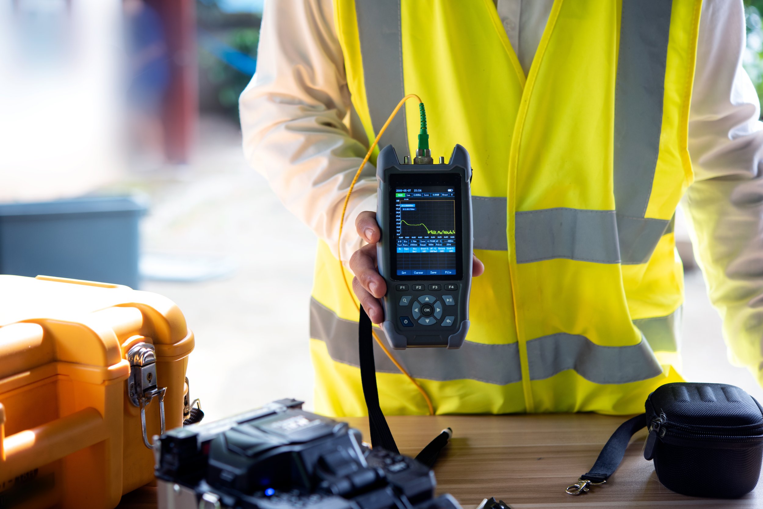
An aerial span can look finished from the ground and still fail the only test that matters. The cable is lashed, the slack is stored, the drops are hung, and the line looks clean against the sky. None of that proves the fiber will carry light the way the design requires. The proof is the acceptance test, and on most builds that test is an OTDR trace.
We have already covered how to calculate a loss budget during design. The OTDR is how a crew confirms the finished span actually lives inside that budget. If you own a network, or you are about to accept one from a contractor, knowing how to read the trace is how you tell a good build from one that will cause problems later.
What the OTDR Is Doing
An optical time domain reflectometer works a little like radar. It sends a high-powered pulse of light down the fiber and measures the light that comes back, both the natural backscatter from the glass itself and the sharper reflections off connectors and splices. Because it measures from one end, a technician can characterize an entire span without a second person at the far end, which is a real advantage on a long aerial route.
The result is a trace, which is a graph of returned optical power against distance. Distance runs along the horizontal axis, and optical power in decibels runs up the vertical axis. The line slopes downward from left to right because the fiber attenuates the signal as it travels. Every feature on that line, every slope and spike and step, is telling you something specific about the span. Reading it well is a skill that takes training and practice, and the Fiber Optic Association reference on OTDRs is a solid neutral starting point for anyone learning the fundamentals.
The Slope Is the Fiber's Health
The steady downward slope between events is the fiber's attenuation, measured in decibels per kilometer. For standard single-mode fiber, you should see roughly 0.35 dB per kilometer at 1310 nanometers and about 0.20 dB per kilometer at 1550 nanometers. A slope that is steeper than expected across a section is a warning. It can point to a stressed or pinched fiber, a tight bend, or handling damage that happened during installation.
This matters on aerial plant specifically, because a lashed line lives with tension, wind, and temperature swings. A section that reads a little steep on the acceptance trace is exactly the kind of thing that gets worse over a few storm seasons. Catching it at turn-up is far cheaper than chasing it after the span is energized and in service.
Reflective Events and Non-Reflective Events
Two kinds of events show up on the trace, and the difference between them tells you what you are looking at.
A reflective event appears as a sharp upward spike followed by a step down. Connectors and mechanical splices cause these, because the small air gap or index change at the junction reflects part of the pulse back toward the instrument. The height of the spike is the reflectance, sometimes called optical return loss, and it is expressed as a negative number. An angled connector, the SC/APC type used at most hardened interfaces, should read at or below negative 60 decibels, meaning very little light bounces back. A higher reflectance number is a signal of a dirty end face, a poor mate, or contamination.
A non-reflective event appears as a step down in the trace with no spike ahead of it. That is almost always a fusion splice. The size of the step is the splice loss, and on single-mode fiber a good fusion splice should measure a tenth of a decibel or less. A step larger than about three tenths of a decibel is worth flagging and usually worth re-splicing. On an aerial build, those splices live inside the closures along the run and at the terminals that feed the drops, which is where the multiport service terminals hand off to the subscriber.
Dead Zones, Launch Fibers, and the First Connection
Right after the launch pulse, the instrument is briefly blinded by its own reflection. That blinded stretch is the dead zone, and any event inside it cannot be measured accurately. This is why a proper test uses a launch fiber, a spool of fiber placed between the OTDR and the span under test. The launch fiber pushes the dead zone off the front of the actual cable plant so the very first connector can be measured instead of lost in the blur.
A receive fiber on the far end does the same job for the last connector. Without both, the two most important connections on the span, the ones at each end, are the ones you cannot verify. A trace submitted without launch and receive fibers is not a complete acceptance test, and it is fair to send it back.
Bidirectional Testing and Gainers
Here is a detail that separates a careful acceptance package from a sloppy one. When two fibers with slightly different backscatter properties are joined, the OTDR can read the same splice as high loss from one direction and low loss from the other. In some cases the trace even shows an apparent gain at the splice, which is physically impossible and is known as a gainer. It is an artifact of the measurement, not a real result.
The fix is to test from both ends and average the two directions. Bidirectional testing is the standard for a reason, and on a build with multiple splice points it is the only way to get honest per-event numbers. If a contractor hands you a single-direction trace and calls the span certified, the numbers are not as trustworthy as they look.
What a Passing Acceptance Test Looks Like
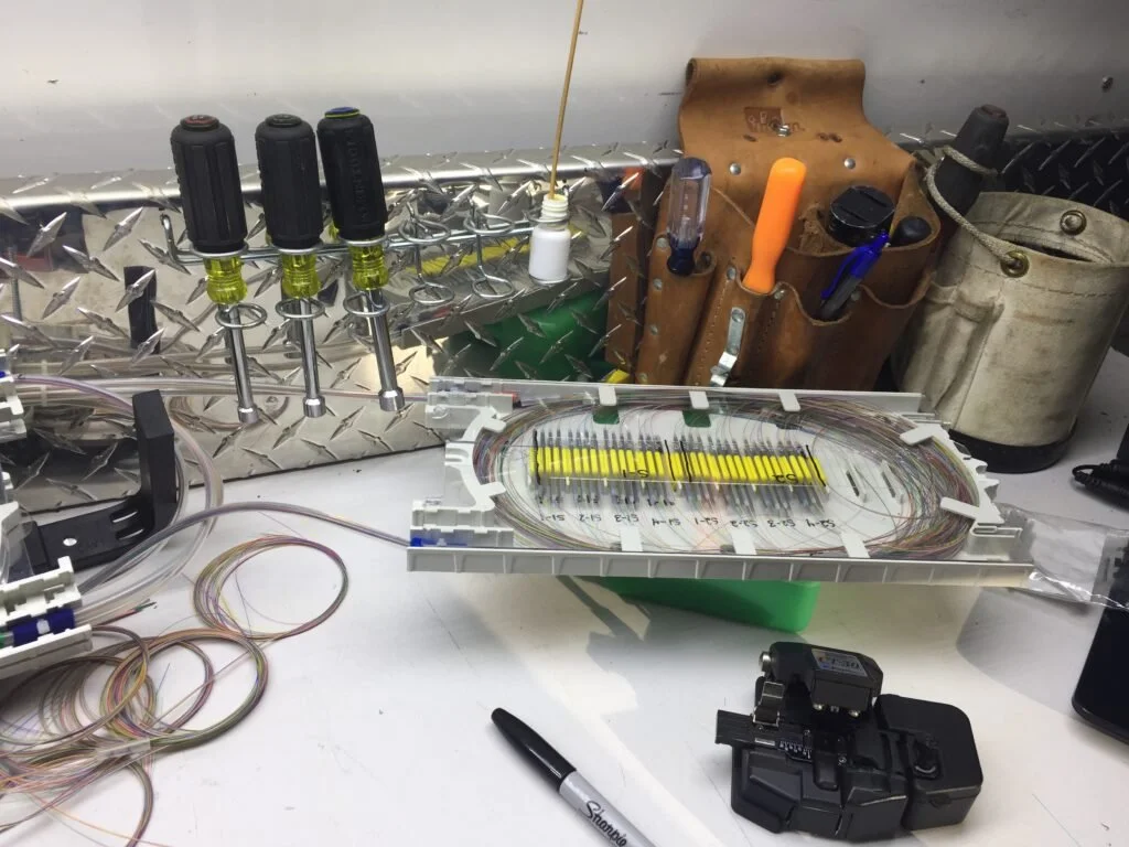
A clean acceptance trace on an aerial span shows a straight, predictable slope at the expected attenuation, splices well under a tenth of a decibel, connectors reading well below negative 60 decibels of reflectance, and a total end-to-end loss that sits inside the loss budget calculated during design. The event table generated by the OTDR should list every connection and splice at its measured distance, and those distances should match the build.
One useful reality check is length. The OTDR measures the fiber, not the cable, and the fiber usually runs about one percent longer than the cable itself because of the way it sits inside the jacket. A trace whose length is wildly off from the as-built footage is a sign that something does not match the records.
The OTDR Is Not the Whole Story
It is worth being clear about what the OTDR does and does not do. It builds a diagnostic map of the span and shows where every event is and how it behaves. It does not measure absolute end-to-end loss the way an optical loss test set, a light source and power meter, measures it directly. Many well-written project specifications require both, one for the true insertion loss number and one for the event-by-event picture. A package that includes only one and calls the job tested is incomplete.
Both belong in the closeout documentation. Every trace, every loss number, and every event table should land in the as-built package so the network owner has a baseline to compare against for the life of the plant. When a storm takes a span down years later, that original trace is what tells the restoration crew what normal looked like.
Why This Belongs in Every Contract
A contractor who tests thoroughly and documents completely is protecting your network, and one who cannot produce clean bidirectional traces with launch and receive fibers is a risk. Incomplete or missing test results are one of the clearest warning signs that a build was not held to standard. The trace is not paperwork for its own sake. It is the record that proves the span will perform, and it is the reference you will lean on every time something changes down the road.
Work With a Crew That Documents the Whole Build
At TermLink Solutions, acceptance testing is part of the job, not an afterthought. We build aerial fiber across Pennsylvania and the Northeast, and every span we turn over comes with the documentation to back it up, from bidirectional OTDR traces to complete as-built records. If you are planning a build, accepting one from another contractor, or trying to make sense of a test package you were handed, we are glad to help. Call us at (814) 243-9914 or reach out through our contact page, and we will walk your project through it.
