

Single-Mode or Multi-Mode: What Changes in the Field, and Where Multi-Mode Still Wins
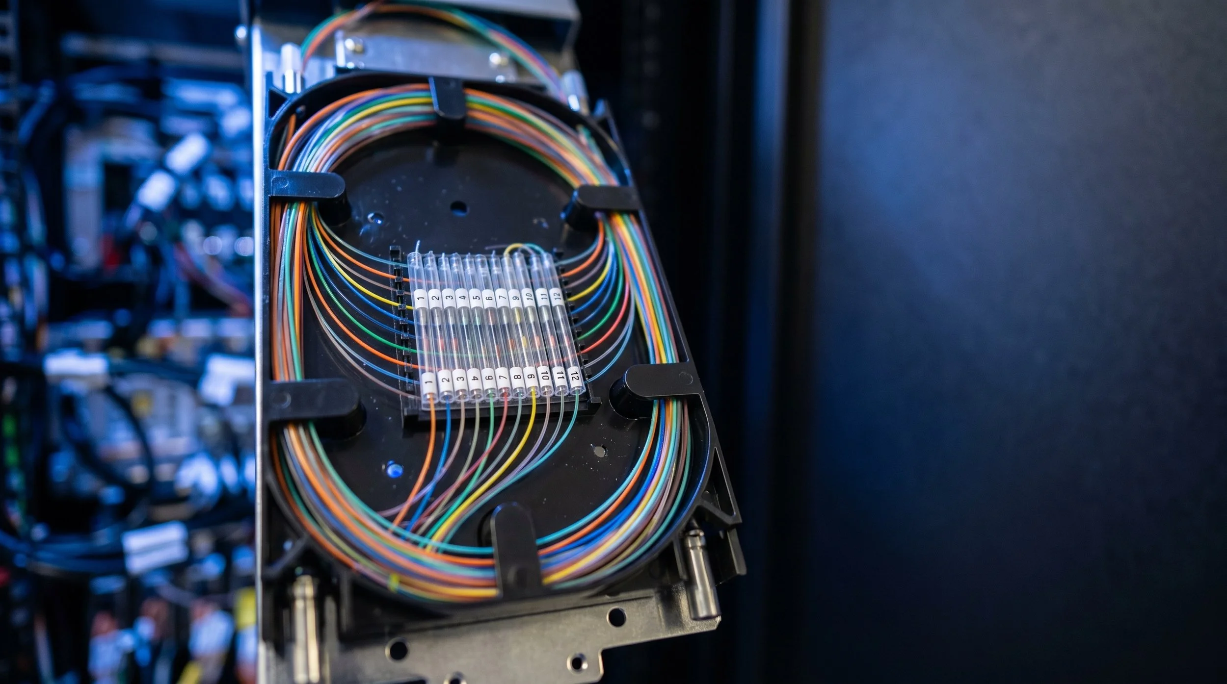
Everything hung on a pole line is single-mode. That is not a preference or a house rule, it is the only answer that works once a route leaves a building, and it has been the only answer for a long time.
That settled fact makes it easy to stop thinking about the question entirely, which is a mistake. Multi-mode is not obsolete. It is thriving in specific places, and outside plant crews run into it at exactly one predictable point: the wall where the network comes indoors. Knowing what changes at that boundary, and why, prevents a category of field problem that is genuinely difficult to diagnose after the fact.
The physical difference
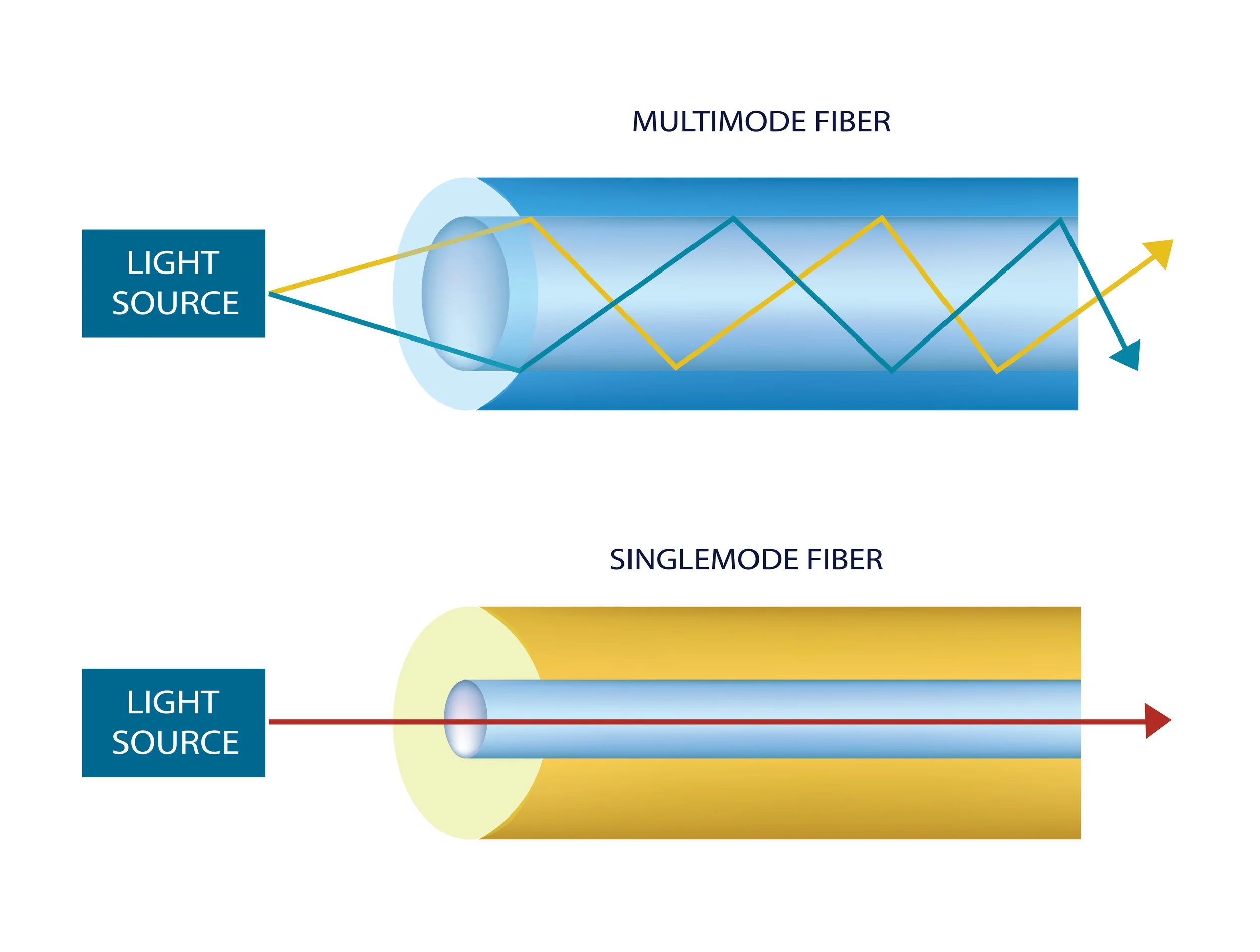
Single-mode fiber has a core roughly 8 to 10 microns across, inside a 125 micron cladding. That core is narrow enough that light travels essentially one path down it. No modal dispersion, which means the signal holds its shape over very long distances.
Multi-mode fiber uses the same 125 micron cladding but a much larger core, either 50 or 62.5 microns depending on grade. Light entering that core takes many paths at once. Those paths have different lengths, so the pulse spreads as it travels, and that spreading is what limits how far a given data rate can go.
The wavelengths differ too. Single-mode systems operate at 1310 and 1550 nanometers. Multi-mode operates at 850 and 1300. An OTDR configured for one will tell you nothing useful about the other.
Why outside plant is single-mode, without exception
Distance settles it. A PON serves subscribers up to roughly 20 kilometers from the head end on single-mode. Multi-mode measured in hundreds of meters cannot participate in that conversation at all.
Capacity settles it again. The cable you hang today has to carry whatever the network needs in twenty years, and single-mode has repeatedly absorbed enormous increases in data rate through electronics changes at each end while the glass stayed put. Multi-mode has needed new fiber grades to keep up.
Cost has also flipped over the years. Single-mode cable is generally the less expensive glass now, and the transceiver price gap that historically favored multi-mode has narrowed considerably. For any run that leaves a building, the analysis is not close.
What changes when you splice multi-mode
The intuition here is backwards from what most people expect.
A larger core is more forgiving of lateral offset, so a mass fusion or fixed v-groove splicer that would produce mediocre results on single-mode can do acceptable work on multi-mode. Single-mode is the demanding one on alignment, which is why core alignment splicers exist. Industry generic requirements for single-mode splicing systems have historically set loss expectations around 0.2 dB for passive alignment and 0.1 dB for active alignment, and that gap is the whole reason core alignment equipment is worth its price.
Multi-mode has a different problem, and it is worse in practice. Splicing a 62.5 micron fiber to a 50 micron fiber creates a real, direction-dependent loss. Light going from the larger core into the smaller one loses a substantial fraction that never makes it. Going the other direction loses very little. A one-way OTDR shot will show a large loss in one direction and something that looks like a gain in the other, and neither number is the truth.
Mixed multi-mode grades inside one building are common, because plants get extended in phases across years. If a splice joins an original 62.5 micron backbone to a newer 50 micron run, the link may pass at a low data rate and fail when someone upgrades the optics. That is a difficult fault to trace years later, and the fix is documentation at install time rather than diagnosis afterward.
What changes when you test multi-mode
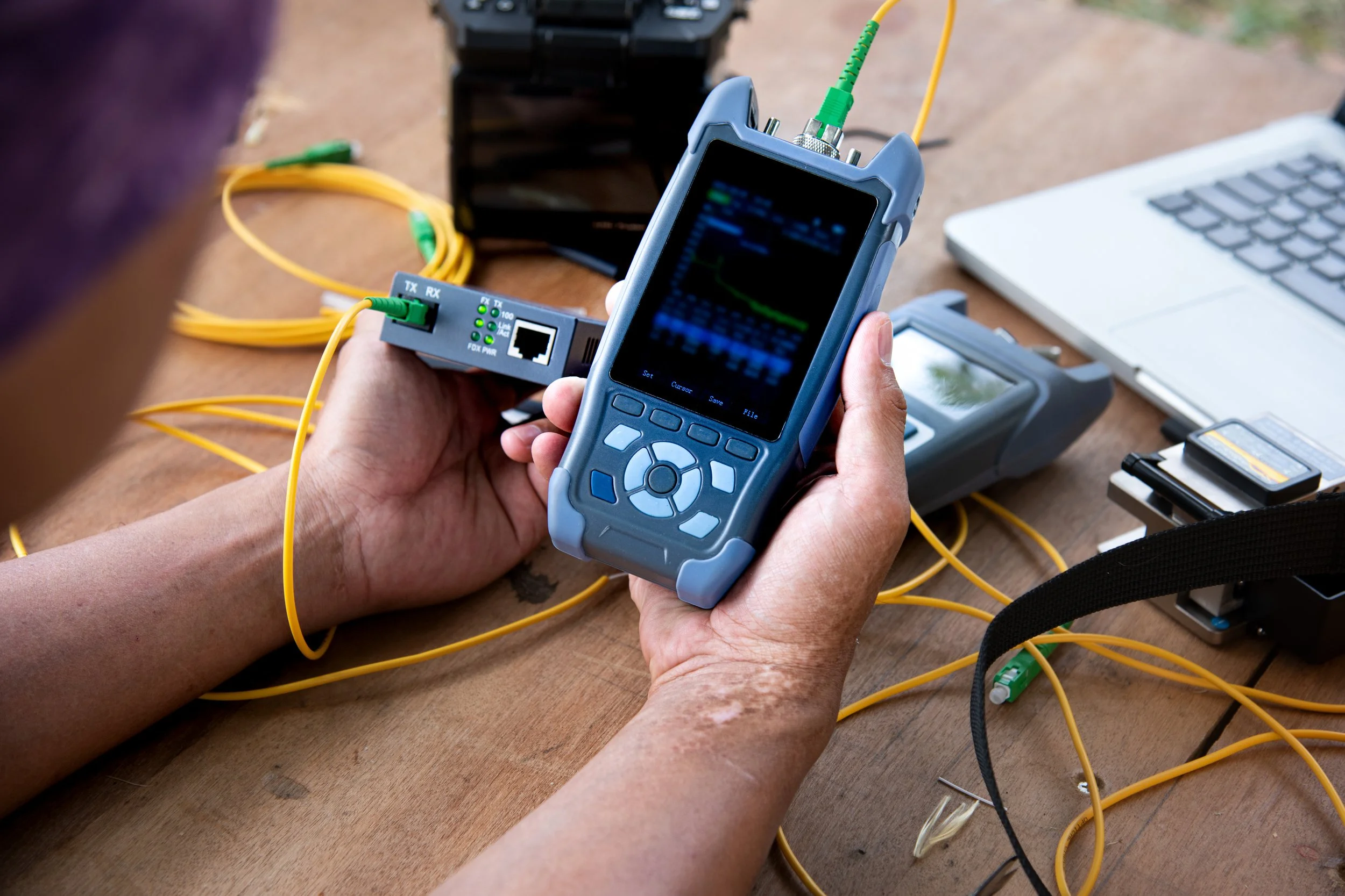
This is the part that catches outside plant crews, because the habits that produce good single-mode results produce unreliable multi-mode results.
Multi-mode loss measurement depends heavily on how light is launched into the core. An overfilled launch, where power is spread across the whole core and beyond, produces pessimistic loss readings, and an underfilled launch concentrated in the center produces optimistic ones. The same link can measure very differently on two instruments for no reason other than launch condition.
The industry answer is encircled flux, standardized in IEC 61280-4-1, which defines an acceptable power distribution so that results are repeatable regardless of whose meter you are holding. Practically, that means an EF-compliant source or a modal conditioner, and reference grade jumpers.
OTDR work on multi-mode has the same issue in a different form. An OTDR emits a narrow coherent pulse that fills the core differently than the VCSEL sources in the actual transceivers, which can produce apparent gain events at connectors that are not real. A mandrel wrap or an EF-compliant launch cord conditions the modal distribution before the pulse enters the link and removes most of that artifact.
If you take one thing from this section, take this: a bidirectional average is not optional on multi-mode, and neither is a conditioned launch.
Where multi-mode still makes sense
Three cases hold up.
The first is short-reach links at scale, particularly inside data centers. At 850 nanometers, VCSEL-based optics are inexpensive and draw little power, and across thousands of links the transceiver savings dominate the cable cost entirely. OM4 supports 10 gigabit short reach out to roughly 400 meters and 100 gigabit short reach to roughly 150 meters, which covers most inside-the-building topologies comfortably.
The second is an existing plant that already works. If a campus or building has a sound OM3 or OM4 backbone and every application in use fits inside its limits, replacing it buys nothing. Extending it with matching fiber is usually the right call, and the discipline is matching the grade exactly rather than mixing.
The third is equipment with fixed multi-mode interfaces. Industrial controls, machine vision, and older audiovisual gear frequently ship with multi-mode optics and no single-mode option. The link is short, the equipment is not changing, and the fiber follows the hardware.
What does not hold up is running a new multi-mode for anything that leaves a building, or specifying it because it was the standard the last time someone looked.
The handoff at the building
This is the practical point for an outside plant crew.
The single-mode aerial plant terminates at an entrance facility. Inside, the customer may have a multi-mode backbone. Those two do not splice together into a working link. The mode field mismatch produces high, direction-dependent, unstable loss, and while a bit of light will get through, it is not a supported design and it will behave unpredictably as data rates rise.
The correct boundary is an active one. The single-mode side terminates, the multi-mode side terminates, and a transceiver or media converter bridges them. Establish that boundary in the design rather than discovering it during turn-up.
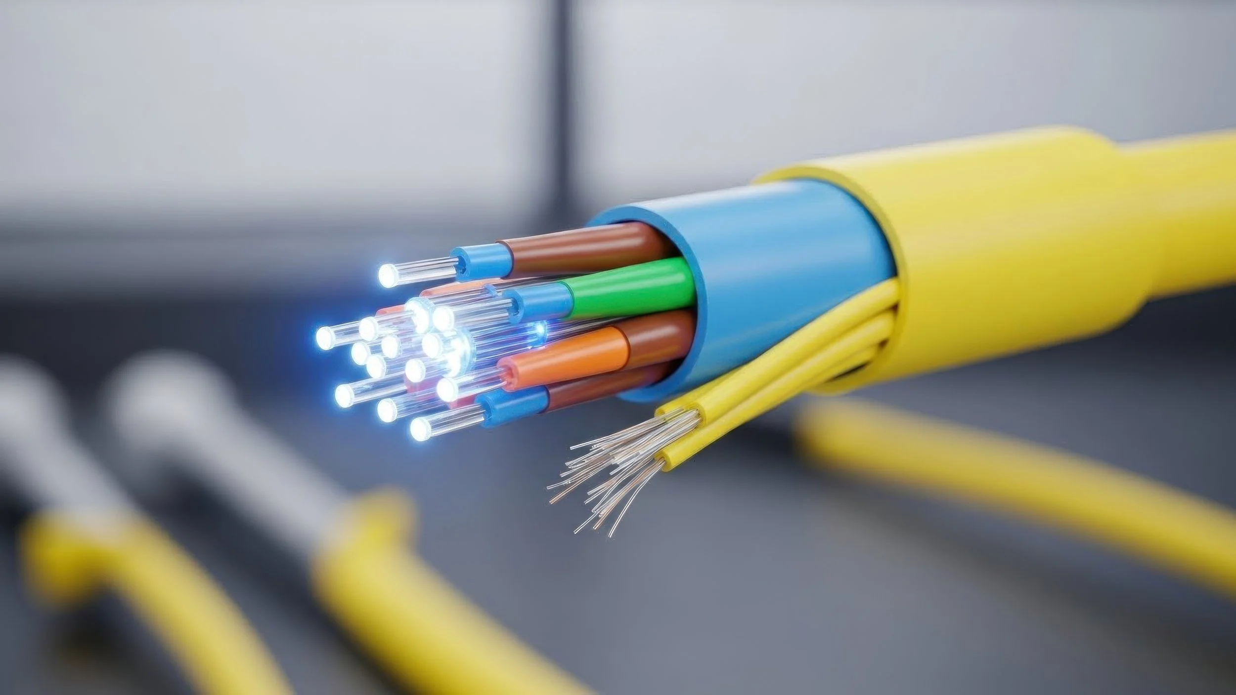
Documentation is the companion discipline. Jacket color carries most of the information: single-mode is yellow, the older 62.5 and 50 micron grades are orange, laser-optimized OM3 and OM4 are aqua, and OM5 is lime green. Record the fiber type and grade in the as-built package at every termination, because the next person to touch it will not have anyone to ask.
The practical takeaway
The outside plant is single-mode and the question is settled. Multi-mode is alive and correct in short-reach, high-density, and legacy-plant situations, and it demands different splicing tolerances, different test wavelengths, and conditioned launch to measure honestly. The failure mode is not choosing wrong at the design stage. It is a crew treating a multi-mode link like a single-mode one, or splicing across the boundary because the cladding happened to be the same size.
TermLink Solutions builds, splices, and tests single-mode aerial fiber plant for ISPs, municipalities, businesses, and private landowners nationwide. If your build terminates into an existing building network, our crews can scope the entrance facility and the handoff so the boundary is designed rather than improvised.
