ADSS vs. OPGW vs. Figure-8: Choosing the Right Aerial Fiber Cable for Your Build
Every aerial fiber project starts with a cable selection decision, and the decision is rarely as simple as picking whatever a distributor has in stock. The three dominant options for overhead deployment, all-dielectric self-supporting cable, optical ground wire, and figure-8 cable, each solve a specific construction problem and fit a specific type of pole line. Choose wrong and the project either costs more than it should or creates operational problems that surface years later during storm restoration, make-ready disputes, or network expansion.
This guide breaks down what each cable type is, where it makes sense, and how network owners, ISPs, municipalities, and contractors should think about the decision when scoping a new aerial build.
ADSS: The Workhorse of Distribution Pole Aerial Fiber
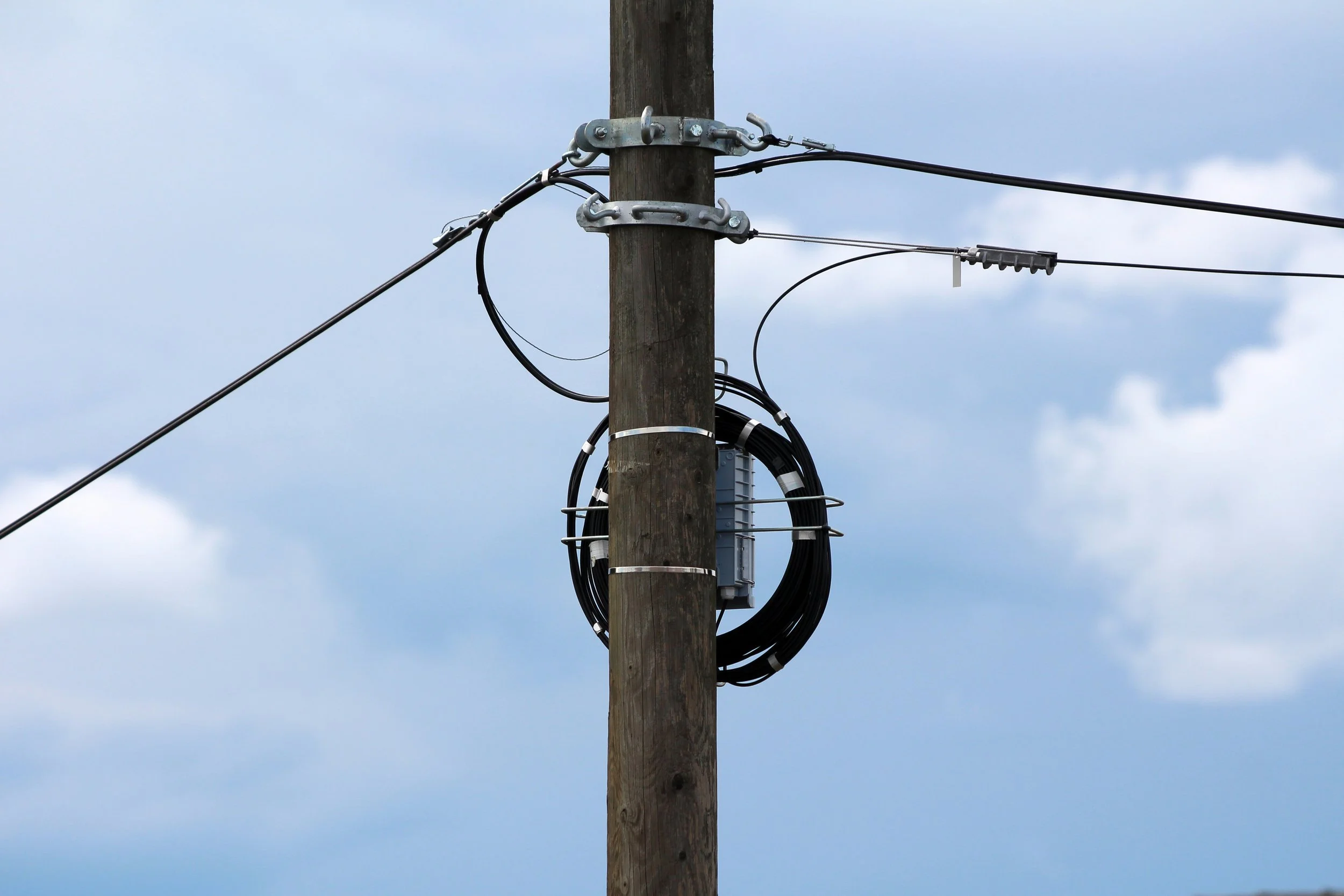
All-dielectric self-supporting cable, known throughout the industry as ADSS, is the most common aerial fiber cable installed on distribution-class utility poles in North America. The name describes exactly what it is: a cable with no metallic components that supports its own weight between poles without a separate messenger strand. A typical ADSS construction has optical fibers inside gel-filled loose tubes, stranded around a non-metallic central strength member made of fiberglass-reinforced plastic, surrounded by aramid yarn for tensile strength, and protected by a polyethylene outer jacket.
The appeal of ADSS comes from what it removes from a project. Because it has no metallic elements, it can be installed in the supply space of a live energized power line. Because it is self-supporting, there is no messenger strand to pre-install, tension, and ground, which means a single installation pass instead of two. Standard ADSS designs support spans from a few hundred feet up to roughly a thousand feet, with long-span variants reaching several thousand feet between supports. Fiber counts typically range from 12 to 432, with 144-count and 288-count designs common on modern FTTH and middle-mile builds. The IEEE 1222 standard governs the construction and testing requirements for ADSS in electric utility environments.
ADSS has two main weaknesses every designer has to engineer around. The first is tracking and dry-band arcing on high-voltage lines, where electric fields on the cable jacket combined with surface moisture can degrade the jacket over time. Track-resistant jacket compounds solve this but cost more and have to be specified at the time of order. The second weakness is exposure to gunfire damage in rural areas, where a single shotgun blast can sever fibers or compromise the jacket and allow water intrusion. These are known tradeoffs, not dealbreakers, and they are why ADSS specification requires attention to span length, voltage class, and environmental exposure.
OPGW: The Transmission-Line Solution That Does Two Jobs
Optical ground wire, or OPGW, is a fundamentally different product from ADSS even though it can look superficially similar once installed. An OPGW cable combines the functions of a transmission-line shield wire with fiber-optic telecommunications in a single cable. The construction contains a small stainless steel or aluminum tube holding the optical fibers at the center, surrounded by outer layers of aluminum-clad steel and aluminum alloy wires that provide mechanical strength and a conductive path to ground.
OPGW replaces the traditional static wire at the top of a transmission tower. The conductive outer layers bond adjacent towers to earth ground, shield the high-voltage phase conductors below from lightning strikes, and conduct short-circuit fault current to ground. At the same time, the fibers inside carry communications for the utility's own protective relaying, SCADA, and data needs, and additional fibers are frequently leased or sold to third-party telecom operators. The IEEE 1138 standard defines the testing and performance requirements for OPGW cables on electric utility power lines.
Because OPGW performs as a structural and electrical element of the power line, it is engineered to a completely different set of requirements than ADSS. It has to survive lightning strikes without damaging the fibers, carry fault current measured in thousands of amp-squared-seconds without melting, and hold up under the ice and wind loads that govern transmission line design. The result is a cable that is more expensive per foot, requires specialized installation hardware, and generally has to be installed during a planned outage or through live-line techniques that only qualified line crews can perform.
OPGW is the wrong choice for almost any distribution-class aerial fiber build. It is the right choice when a utility is rebuilding or re-shielding a transmission line and wants to capture telecommunications capacity at the same time. Telecom providers and municipal broadband projects generally encounter OPGW as something they lease capacity on, not something they build themselves.
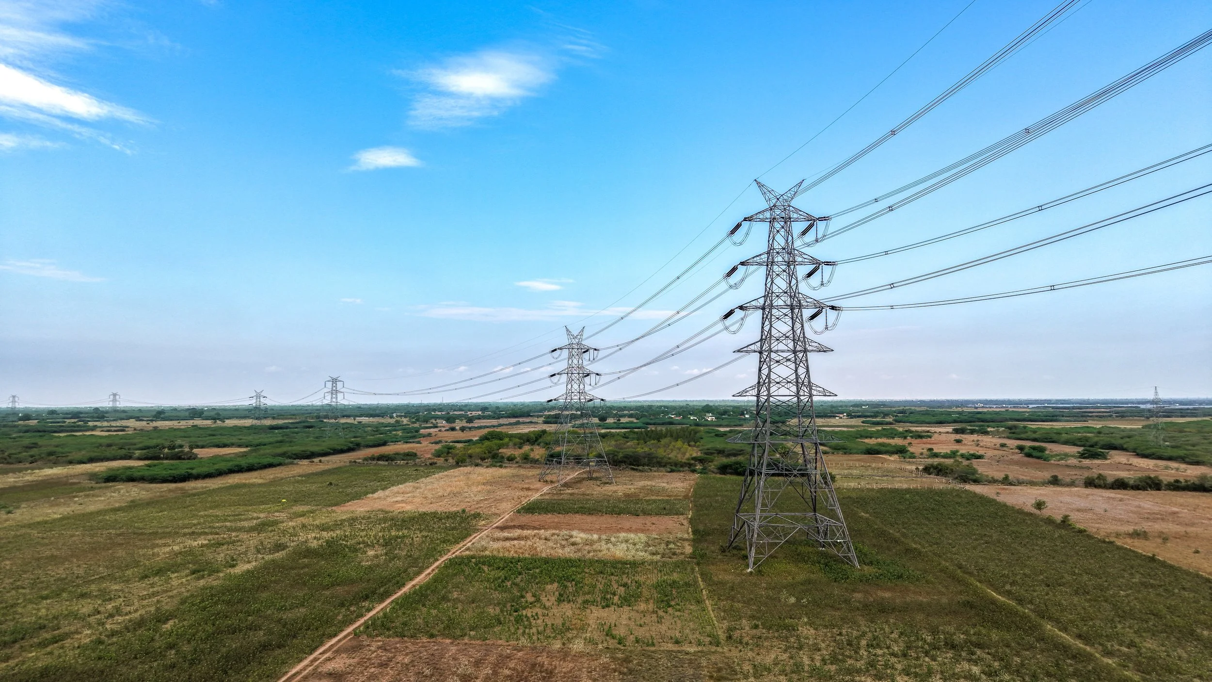
Figure-8: The Pre-Lashed Messenger Solution
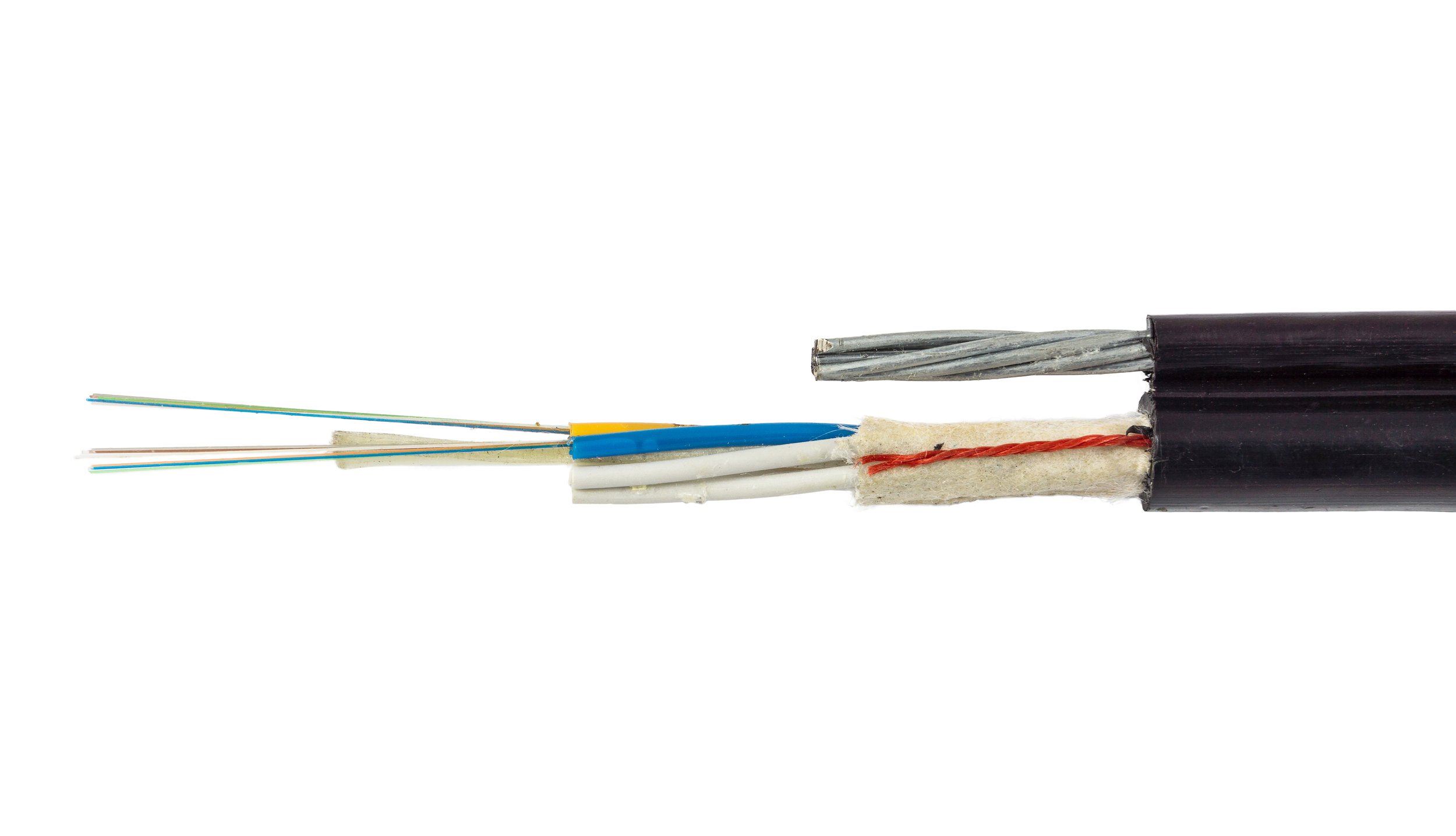
Figure-8 cable, sometimes called self-supporting or messenger-integrated cable, takes a different approach entirely. The cable is manufactured with a galvanized steel messenger strand bonded to the fiber-optic core through a shared polyethylene jacket, creating a cross-section that looks like the number eight from the end. The messenger carries the mechanical load and the fiber unit carries the signals, all in a single cable that installs in one pass without a separate lashing operation.
Figure-8 solves a specific problem: it removes the lashing step from aerial fiber installation. On a traditional aerial build using loose-tube fiber cable, a crew first hangs a separate messenger strand, tensions it, grounds it, and then makes a second pass with a lasher to spin a helical wire around the fiber cable and messenger. Figure-8 collapses that two-pass operation into one, saving time and crew hours on straightforward pole routes.
The tradeoffs are real. Figure-8 is heavier per foot than ADSS of the same fiber count, which can matter on poles with tight loading margins. It does not handle mid-span access as cleanly as ADSS because separating the messenger from the fiber core during a mid-span splice adds time and introduces a potential failure point. It is also less common on modern high-fiber-count builds, where ADSS has largely taken over the FTTH and middle-mile market. Figure-8 remains popular on cable-television plant extensions, short spans, and maintenance work where matching the existing plant is a priority.
How to Actually Choose Between Them
The decision between ADSS, OPGW, and figure-8 almost always collapses to three practical questions. The first is what kind of pole line the fiber is going on. Transmission towers point strongly toward OPGW. Distribution poles, whether electric or telephone, point toward ADSS or figure-8. That single distinction eliminates most of the field before any other analysis begins.
The second question is span length and loading environment. Standard ADSS handles most distribution spans comfortably. Long-span ADSS designs extend that range into specialized crossings. Figure-8 is typically limited to shorter spans because the messenger is sized for lighter duty than a standalone transmission-grade cable. Projects with unusually long spans, river crossings, or heavy ice loading have to account for the actual engineering conditions, not a catalog default.
The third question is what the project needs five or ten years out. Mid-span access for adding new service drops or splicing in a fiber distribution hub is cleaner on ADSS because the construction allows easier access to individual buffer tubes. High fiber counts for future capacity expansion are easier to specify on ADSS and OPGW than on figure-8. Projects chasing grant funding tied to specific speeds and service levels should specify cable types that accommodate future upgrades without a full plant rebuild.
The Specification Mistakes That Cost Projects Money
The most common specification failure is choosing cable type based purely on cost per foot without accounting for total installed cost. Figure-8 has a lower material cost per foot than lashed construction in some markets, but the labor savings often get eaten back up on complex routes with a lot of mid-span work. ADSS looks expensive compared to lashed cable on materials, but a single installation pass and no messenger procurement often brings total installed cost below lashed alternatives.
Another common mistake is under-specifying the jacket for actual field conditions. A standard polyethylene ADSS jacket installed in the supply space of a 25 kV distribution line without track-resistant compounding will fail years sooner than a properly specified cable, showing up as jacket erosion and fiber attenuation during routine OTDR testing. The cost difference at purchase is modest. The cost difference during a premature plant rebuild is significant.
A third failure mode is ordering cable without confirming hardware compatibility. ADSS requires matched dead-ends, suspension clamps, and storage hardware rated for the specific cable diameter and weight. OPGW requires specialized hardware designed for the transmission environment. Mixing cable from one manufacturer with hardware from another without confirming compatibility leads to hardware failures that can take years to manifest.
Matching the Cable to the Project
Aerial fiber cable selection is not a generic spec sheet exercise. It is an engineering decision that has to account for the pole line, the span and loading environment, the operational future of the network, and the hardware ecosystem that will support the cable across its service life. Contractors who build aerial fiber at scale treat cable selection as part of the design phase, not as a procurement afterthought.
TermLink Solutions works with ISPs, municipalities, electric cooperatives, and network owners across Pennsylvania and beyond to specify, install, splice, and test aerial fiber the right way. Our crews have installed ADSS, OPGW, and figure-8 cable across every type of pole line and environmental condition the Northeast throws at them. If you are scoping a new aerial build or evaluating an existing plant for expansion, reach out to our team and let's make sure your cable choice sets your network up for the long run.